Document Type : Original Article
Authors
1 Department of Chemical (Process) Engineering, North Tehran Branch, Islamic Azad University, Tehran, Iran
2 Department of Chemical Engineering, North Tehran Branch, Islamic Azad University, Tehran, Iran
Abstract
In the present study, the structure and operation of solid oxide fuel cells and types of ammonia-water adsorption cycles were evaluated. When the fuel cell temperature is 1100 K, the fuel cell current density is 1.17 and the steam to carbon ratio enters the system is 2, the electrical efficiency of the combined system (HHV) is %50. Using the Aspen Plus optimizer software, we optimized the hybrid system with 500 kW power generation. By performing the optimization, the required investment cost for the hybrid system was obtained on average $1800. Also, the appropriate range of current density and voltage were found to be 0.35 - 0.6 and 0.72 – 0.8 V, respectively. Therefore, based on the calculations and optimization, our cycle has an average cost of 1800 $/kW. The point to be noted is that the cost per capita is 6000 kW. According to economic principles if the amount of power generation increases, the amount of cost per unit of power generation will decrease. A hybrid heating system (gas turbine + steam turbine) with a production capacity of 140 MW has an average cost 1100$/kW. Therefore, it is necessary to reduce the cost of the cycle per unit of production capacity by increasing the scale of the desired cycle in the industrial units to be competitive with conventional thermal power plants. Of course, do not forget that the efficiency of our desired cycle is higher than the efficiency of conventional thermal power plants.
Graphical Abstract
)
Keywords
Main Subjects
Introduction
Due to predictions made about the energy crisis in the coming years and the fact that fossil fuels will run out in the future, we must move toward replacing older systems with the most efficient systems for the production of secondary energy (electricity-heat) [1-3]. Furthermore, using new systems and designs, the environmental crisis created by fossil fuels can be predominately overcome [4-6]. In recent years, fuel cells have been considered due to their high efficiency, environmental compatibility, simplicity in terms of maintenance, variety in fuel consumption, lack of moving parts, and no vibration and high exhaust gas temperatures. One of the most wide used cells is the solid oxide fuel cell [7]. The high operating temperature of solid oxide fuel cells has made it possible to use various fuels such as natural gas directly in this type of fuel cell [8]. These types of cells convert the chemical energy of the fuel directly into electrical energy due to the difference in the chemical potential of oxygen at the anode and cathode [9-11]. The oxygen ion produced by the electrolyte travels from the cathode to the anode, leading to the oxidation of the fuel. One of the most important things that is very effective in increasing the efficiency of this type of system is the optimal use of heat from exhaust gases. This heat is used to generate electricity or provide the required heat to the building in a separate cycle. This project uses the heat of the exhaust gases from the fuel cell in the absorption cooling cycle [12]. Chillers are among the most critical equipment in cooling that can be generally divided into: compression chillers and absorption chillers. In general, compression chillers use electrical energy, and absorption chillers use thermal energy as the primary cooling source. Absorption refrigeration technology is an excellent method for central air conditioning in installations with additional heat and can provide the steam or hot water needed to operate the chiller [13].
In a general classification, absorption chillers can be classified into water and ammonia absorption chillers and lithium bromide and water absorption chillers. In fact, in each adsorption refrigeration cycle, there is an adsorbent fluid and a refrigerant fluid, based on which the above division has been done. The refrigerant ammonia system is a water-absorbing medium in the water and ammonia system. In the lithium bromide and water system, the water refrigerant and the adsorbent are lithium bromide solutions. Absorption chillers are devices that can create refrigeration (cold water production) in the evaporator section due to the absorption and repulsion of refrigerant by the adsorbent (respectively in the absorber and generator sections), which of course, for complete refrigeration cycles require a relatively low-temperature source (cooling water) in the condenser section for refrigerant distillation. Absorption chillers need a heat source for the cooling process [14]. In direct flame absorption chillers, this source of heat energy is generated by the combustion of gas inside the generator.
Basic information and Simulation
Basis of Work of Hybrid System
Solid oxide fuel cells have a relatively high temperature (about 1100 °C). Therefore, the exhaust gases from the fuel cell have an excellent potential for use in different heating cycles. Typically, solid oxide fuel cell has an electrical efficiency of 40-60%, which increases to 80% by combining it with a simultaneous electricity and heat generation system. The heat generated by the exhaust gases from the cell can be used both directly and indirectly in thermal cycles. The thermal cycle fluidity is the same and interdependent in the direct mode with the fuel cell fluidity. However, in the indirect mode, the thermal cycle fluidity is different from the fuel cell fluidity and uses only the exhaust gases through a heat exchanger. Since the fluid exiting the cell is a gaseous fluid, the work is based on the Brayton cycle. Gas turbines are based on the Brayton cycle.
Simulation result
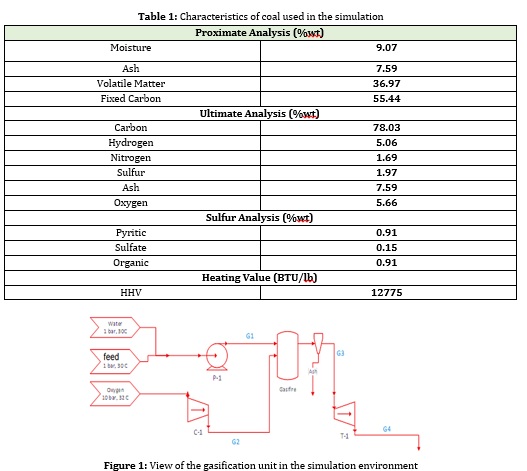
The biomass characteristics used are shown in Table 1.
This section compares the work done with Hoffman's research. This research concerns the integrated design of the combined biomass gasification system and the heating turbine cycle compared with Hoffman's work by performing this simulation by a gas maker and the results are recorded [15].
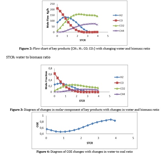
Cold Gas Efficiency (CGE): The ratio of the calorific value of the exhaust gas to the maximum coal calorific value (CGE). And are obtained from the following relation [16].
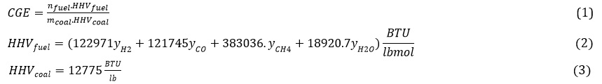
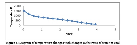
Production capacity of gas turbine: The absolute difference between gas turbine power and air compressor. In the following, the results related to the simulation are examined, and the effect of essential factors and parameters on this simulation is examined. In the process, biomass slurry in water is used, which helps control the temperature of the gas generator and the production of more hydrogen and carbon monoxide and transportation costs, all of which have been examined [17]. Another essential factor that plays an essential role in this process is the rate of air entering the gas generator, the inlet temperature and the amount of power required by the compressor, which has been investigated. As seen in Figures 2, 3 by increasing the flow of inlet water, the concentration and flow of hydrogen and carbon monoxide, being part of the process of fuel cells, is reduced. This is due to the reaction of methane with water vapor, which is not desirable. The water to biomass ratio should be kept in 0.5 to 1.5 to prevent work. However, according to Figure 4, the gas efficiency increases with increasing this ratio, which is also due to more methane production in the gas generator. This can be justified according to the formula (2) and the high calorific value of methane. On the other hand, according to Figure 5, with increasing the water ratio, the temperature of the gas generator decreases sharply, which makes it challenging to use the turbine for heat recovery. Therefore, for almost optimal use of this unit, the incoming water to biomass ratio should be kept in the range of 0.5 to 1.5 [17].
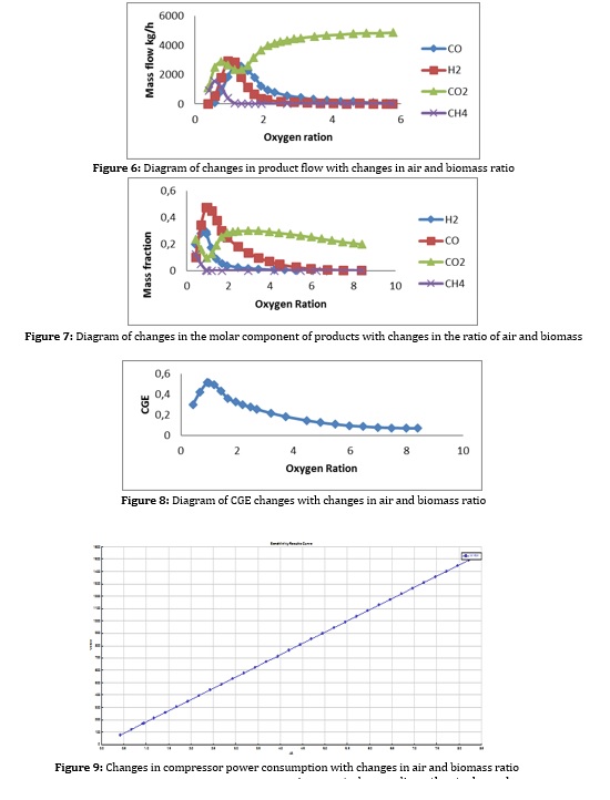
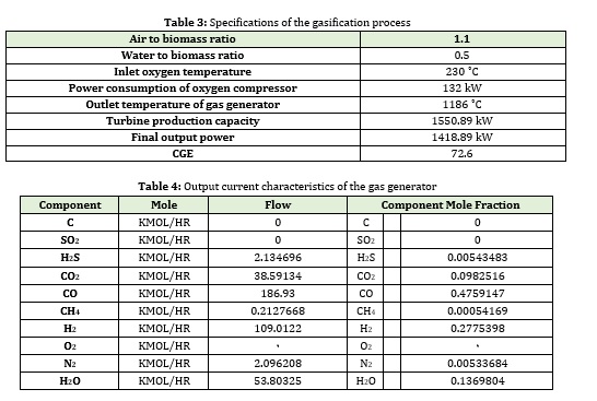
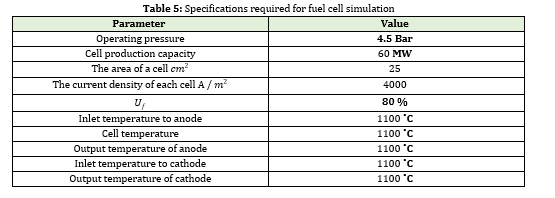
Figures 6 and 7 also reveal the flow rate and concentration of hydrogen with changes in the incoming air to the gasifier, which indicates the re-reduction of hydrogen and carbon monoxide, this time due to the complete biomass fuel in the gasifier. Also, according to Figures 8 and 9, it can be seen that with the increase of inlet oxygen, the gas efficiency decreases and the compressor power consumption increases, so as a result, the oxygen ratio is kept at 1 to 3. Inlet oxygen temperature should also be high if possible [22].
Results and specifications of the final gas generator flow
As expected, regarding other tasks such as double-acting, the ratio of water to biomass is in the range of 0.5 to 1.5, and the ratio of oxygen is between 1 and 2.5.
Fuel cell
The proposed model for fuel cell simulation in this research was examined in previous chapters. In this research, the aim is to design a fuel cell power plant with a power of 6 MW. According to the power cell characteristics revealed in Table 5 and the proposed model for voltage drop, there can be other parameters such as voltage and current. Overall, the number of cells, active area, and power density were calculated. The of all parameters such as current density and temperature on them were examined and compared with other works.
The fuel cell model used in this process is dimensionless and does not depend on the dimensions of the fuel cell.
The evaluation of this model with the rest of the work is shown in Table 5.
According to the information in the table above and the simulations performed, it is clear that the fuel cell model has good accuracy in predicting fuel cell parameters.
Simulation results
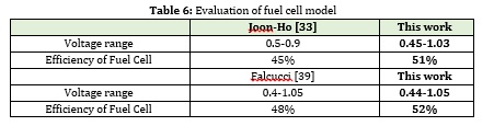
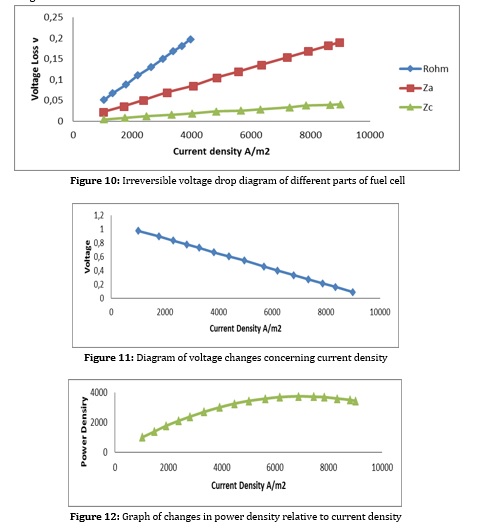
As mentioned, this simulation is to generate 6 MW of power from a fuel cell, which are discussed below. Basic simulation information is also listed in Table 6. In this section, the effective parameters in fuel cell performance are evaluated. As shown in Figure 12, as the current density increases, the cell voltage decreases due to the irreversible voltage drop across the cell shown in Figure 11. On the other hand, increasing the current density in the cell increases the power density in the cell, thus reducing the number and active area in the cell. Therefore, the current density should be determined so that a good balance between voltage and power density is established by increasing the current density. Another factor to consider is the fuel and air required for the fuel cell. Finally, Figure 13 shows the efficiency of the fuel cell relative to the current density, which decreases with increasing current density.
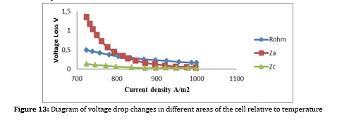
Another factor to consider is the temperature of the fuel cell, which has a significant impact on the electrochemical synthesis of the fuel cell. Which has a significant effect on voltage and consequently on the active area, number of cells, and fuel consumption. Figure 18 depicts the irreversible voltage drop changes with temperature changes. The higher the cell temperature, the lower the voltage drop. However, the temperature can be raised to some extent because the high temperature causes depreciation and additional costs. On the other hand, due to the internal reforming, the cell temperature should not exceed a certain level and should be within a specific range for further conversion. The reduction of voltage drop is also due to the presence of high-temperature catalysts such as nickel, which demonstrates a better performance with increasing temperature.
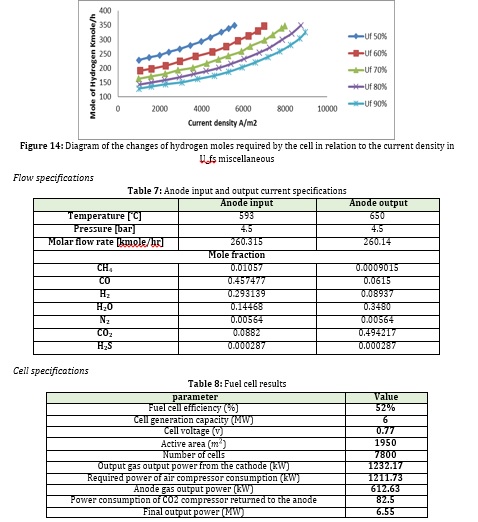
But one of the most critical parameters in determining the performance of a fuel cell is , which indicates the rate of fuel conversion at the anode. The higher this parameter, the better the performance of the fuel cell and the less fuel required for the same power output. In this study, this parameter is considered 80%, but then the effect on the amount of hydrogen consumption at temperature and constant and variable flow density is investigated.
The process of capturing carbon dioxide
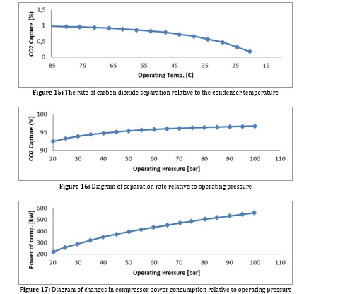
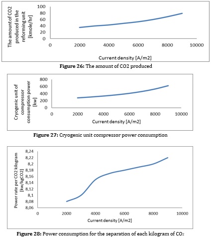
The performance of this process depends on the separation rate, the cooling air conditioner temperature, and the compressor's power consumption. However, due to the difference in the boiling point of carbon dioxide with other feed materials, the process does not require a distillation tower, which is used in most cryogenic processes. Condenser temperature and process operating pressure are two essential factors in simulating a carbon dioxide separation unit that has been investigated. As the temperature of the condenser decreases, the amount of carbon dioxide emitted increases (diagram). The higher the compressor pressure, the more carbon dioxide is released, except that a lower temperature is required for the same amount of separation at higher temperatures, which depends on the amount of evaporator heat in the absorption refrigeration process. Because increasing the pressure increases the power consumption in the process. Analyzes and diagrams related to this process can be seen below:
The simulation results are given below according to the absorption refrigeration process, temperature, and heat load.

Absorption refrigeration of water and ammonia
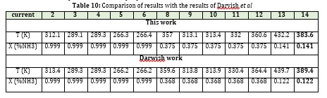
In this section, before reviewing the simulation results of the water-ammonia absorption cycle, the results of the work performed are compared with the simulation results of Aspen Plus. Darvish et al. Studied and simulated the absorption cycle of ammonia and water using an Aspen simulator, which used the PR equation to find the properties of currents. Figure 18 depicts a schematic view of this process. One of the characteristics of this cycle is that it is commercial and its experimental results are available. The overall performance of this cycle is similar to a single-effect cycle. According to the input data of the article [35], the comparison of the results can be seen in the table below.
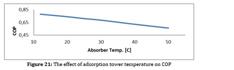
Figures 28 to 31 show the results obtained from the simulation and the effect of essential parameters on the COP.

Combined System Results
Figures 22 to 25 show the effect of density change on important parameters of the hybrid system. The suitable operating range of the hybrid system is 0.47-0.8 V, which is a relevant factor of performance, economic parameters. It is noteworthy that due to the existence of steam turbines to generate electricity from excess heat, the acceptable operating range of the hybrid system has increased. As the current density increases, the cell voltage decreases, and the fuel cell efficiency decreases. The current density increases; this heat is used in the steam cycle to generate additional electricity and prevents a severe reduction in fuel cell performance. As the current density increases, the number of cells decreases due to the increase in power density until it reaches a minimum point and then increases. In addition, by reducing the performance of the fuel cell, more heat is generated inside the cell, and we need more air to control the temperature of the cell. As the inlet air of the system increases, the power consumption of the air blower also increases, and as a result, the system's overall efficiency decreases. Although more heat is generated inside the cell as the current density increases, this heat is used in the steam cycle to generate additional electricity. It prevents a severe reduction in fuel cell performance. As the current density increases, the number of cells decreases due to the increase in power density until it reaches a minimum point and then increases.
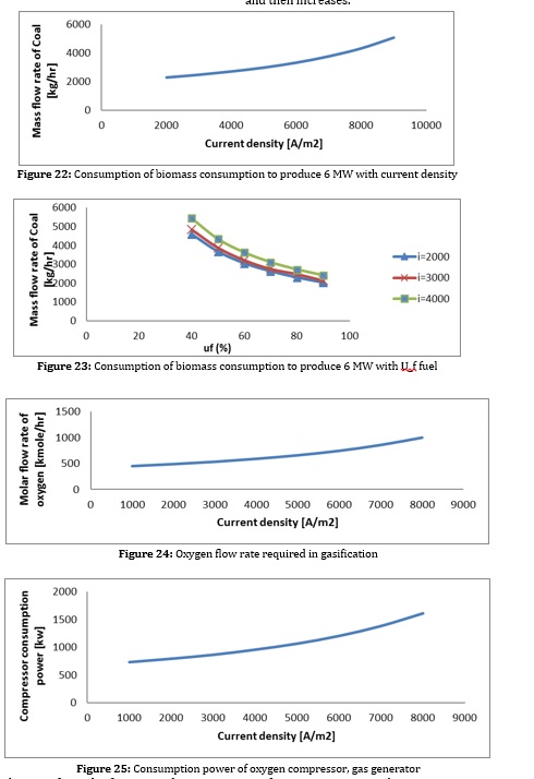
As can be seen from the figures, with increasing current density, the amount of biomass consumed and the air entering the gas generator increases. Increasing the excess air increases the compressor's power consumption and reduces the system's efficiency. On the other hand, increasing biomass consumption increases the volume of CO2 produced in the reforming process. This increases the compressor power consumption and the condenser heat load of the CO2 separation section and increases the separation cost per CO2 unit. Increasing the heat load in the condenser also directly affects the heat load of the evaporator of the absorption refrigeration system and causes an increase in the volume of ammonia and water consumption to supply this heat load, which causes the temperature in the reboiler section to rise and the heat load to rise. All these factors cause the COP of this system to decrease.
As a result, increasing the density increases biomass consumption, decreases fuel cell efficiency, increases the CO2 produced, increases the power consumption to separate each CO2 unit, and reduces the COP of the adsorption refrigeration system. Reducing the fuel cell has the same effect as increasing the current density. (To produce constant power).
Therefore, in a combined system, heat is recovered in four ways and increases system efficiency.
1- Power produced by fuel cell
2- Power generated by the steam turbine
3- Cold produced by the absorption cycle
4- Heat recovered for heating.
Another point that can be mentioned about the definition of electrical efficiency of the whole system is that by converting the cold obtained in the absorption cycle, the equivalent work can be defined as follows:

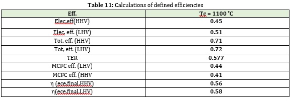
Table 10 shows the values of the different types of efficiencies defined for the combined system and fuel cell mass.
Conclusion
Since it is not possible to study the results of these systems empirically, simulator software is needed. We have used Aspen Plus emulator software to advance our goals. By analyzing the sensitivity on these parts and identifying appropriate performance points, the results include A: The need for internal fuel reforming B: Use of anode and cathode reverse current C: Appropriate voltage and current density range D: Use of ammonia-water single effect absorption cycle and E: Using the Rankin steam cycle. The need for cold generation and the need for cold generation and electricity generation in various sectors, including domestic, commercial and industrial, is of great importance. Therefore, it was necessary to obtain and study different types of systems and work on the operational and structural foundations of different processes to achieve an optimal combination of simultaneous heat and cold production. And finally, according to the presented results, we were able to somehow meet the project's main goal.
Funding
This research did not receive any specific grant from funding agencies in the public, commercial, or not-for-profit sectors.
Authors' contributions
All authors contributed toward data analysis, drafting and revising the paper and agreed to be responsible for all the aspects of this work.
Conflict of Interest
We have no conflicts of interest to disclose.
HOW TO CITE THIS ARTICLE
Pedram Shirzadi, Mir Esmaeel Masomi, Ali Hekmat Nazemi, Fuel Cell Simulation Using Aspen Plus Simulation Software. Chem. Methodol., 2022, 6(3) 197-211
DOI: 10.22034/CHEMM.2022.317992.1403
URL: http://www.chemmethod.com/article_143299.html
ORCID
Mir Esmaeel Masomi:
https://www.orcid.org/0000-0002-2168-4865
- Zhang X., Chan S.H., Li G., Ho H.K., Li J., Feng Z., Power Sources, 2010, 195:685 [Crossref], [Google scholar], [Publisher]
- Dokmaingam P., Irvine J.T.S., Assabumrungrat S., Charojrochkul S., Laosiripojana N., J. Hydrog. Energy, 2010, 35:13271 [Crossref], [Google scholar], [Publisher]
- Andersson M., Yuan J., Sundén B., Energy, 2010, 87:1461 [Crossref], [Google scholar], [Publisher]
- Jawahar C.P., Saravanan R., Sust. Energ. Rev., 2010, 14:2372 [Crossref], [Google scholar], [Publisher]
- Margalef P., Samuelsen S., Power Sources, 2010, 195:5674 [Crossref], [Google scholar], [Publisher]
- Ishak F., Dincer I., Zamfirescu C., Power Sources, 2012, 212:73 [Crossref], [Google scholar], [Publisher]
- BIČÁKOVÁ O., Straka P., Acta Geodyn. Geomater, 2010, 7:175 [Google scholar]
- Paradis H., Andersson M., Jinliang Yuan, and Bengt Sundén. Fuel Cell Sci. Tech., 2011, 8:031014 [Crossref], [Google scholar], [Publisher]
- Wongchanapai S., Iwai H., Saito M., Yoshida H., Power Sources., 2012, 204:14 [Crossref], [Google scholar], [Publisher]
- Akkaya A.V., Sahin B., Erdem H.H., J. Hydrog. Energy, 2007, 32:4600 [Crossref], [Google scholar], [Publisher]
- Barelli L., Bidini G., Gallorini F., Ottaviano A., J. Hydrog. Energy, 2011, 36:3206 [Crossref], [Google scholar], [Publisher]
- Samimi A., Samimi M., Eng. Ind. Res. 2021, 2:1 [Crossref], [Google Scholar], [Publisher]
- Samimi A., Eng. Ind. Res. 2021, 2:71 [Crossref], [Google Scholar], [Publisher]
- Samimi A., Bozorgian A., Samimi M., Eng. Ind. Res. 2022, 3:1 [Crossref], [Google Scholar], [Publisher]
- Gandiglio M., Lanzini A., Leone P., Santarelli M., Borchiellini R., Energy, 2013, 55:142 [Crossref], [Google scholar], [Publisher]
- Brunet R., Reyes-Labarta J.A., Guillén-Gosálbez G., Jiménez L., Boer D., Chem. Eng., 2012, 46:205 [Crossref], [Google scholar], [Publisher]
- Selwynraj A.I., Iniyan S., Polonsky G., Suganthi L., Kribus A., Therm. Eng., 2015, 75:1055 [Crossref], [Publisher]
)